Support

6 Support Entries

Problem:

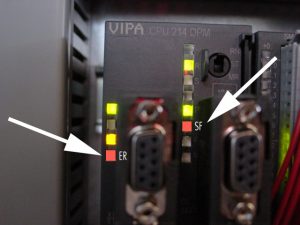
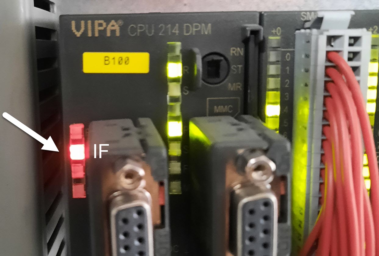
All drives are starting correctly, but the vacuum and welding current are not active.

Possible Causes & Resolutions:

  • Welding pressure has been set below the min. value of 2.0 bar => Check the welding pressure setting value on the precise air-regulator and reset if needed.
  • Solenoid valve welding pressure Y10 does not work correctly  => Check the welding pressure valve Y10. Does the valve switch correctly and do the welding rollers close?
  • Welding rollers are closing and welding pressure is set correct, but no welding pressure value is displayed on the HMI => Check whether the analogue sensor B77 is working correctly or not.


Download PDF here

Possible Causes & Resolutions:

  • No supply of a Profibus participant (slave) on the bus system.
    • Check 24Vdc supply of Linmot controller. Is supplied by 24Vdc terminal X10. For more details check wiring diagram.
    • Check 400Vac supply of Pacemaker. The circuit breaker Q5 may have tripped. For more details check wiring diagram.
  • Address of Profibus on Linmot controller is set wrong.
    • Check the two rotary switch S1 and S2 on front side of Linmot controller. Both should be set according wiring diagram.


  • Dip switch for interface on Linmot controller is set wrong.
    • Check the Dip switch S3 on bottom side of Linmot controller. Dip switch 4 must be set to ON to activate the Profibus interface, all other must be set to OFF.


  • Wrong position of the switch for end resistant on the bus plug.
    • Check all switches on the complete bus system. Follow the cable seriously from first to last Profibus participant . Plug of first Profibus participant and plug of last Profibus participant must be set to ON, all other to OFF.
  • Pacemaker™ settings lost because of empty ram battery
    • Replace battery. You can find more information here => Pacemaker – Support (canman.ch)
    • If the ram battery of the Pacemaker is empty and the settings are lost, the profibus communication may no longer start and also the analogue outputs, which control the speed for the wire drive and downstacker, are switched off (0Vdc).
    • After a battery change, the Pacemaker™ may have to be rebooted 3 – 4 times. To do this, disconnect Pacemaker™ from the mains and reconnect it (fuse breaker Q5 off and on again). Check the parameter settings before start the welding machine. If you have no access please open a ticket to get support => Can Man Support


  • PLC program has been lost due to empty ram battery and missing program on the memory card. Red LED IF is on.
    • Program has to be loaded again by DP/MPI adaptor and laptop with installed Siemens Step7 software or from memory card (MMC) with program file. => Contact Canman.
    • Possibly PLC or memory card are defective and has to be replaced.
    • Important: The ram battery in the PLC cannot be replaced! This is charged when the machine is switched on and guarantees that the program is retained for a maximum of 30 days. If the PLC loses the program due to an empty ram battery, it automatically loads it from the memory card (MMC) when the machine is started. Of course only if a memory card is inserted and there is a valid file on it.


More information about the PLC and explanations of the LEDs “ER,” “SF,” and “IF” can be found in the manual. Link below.

Vipa 214 Manual


NOTE:
The positions of the screws for the sensors B19, B24 and B78 have been set in the factory, and should not be adjusted. If something has changed nevertheless, you should follow the detailed description below.
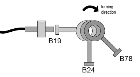
 

B19

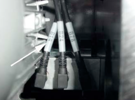
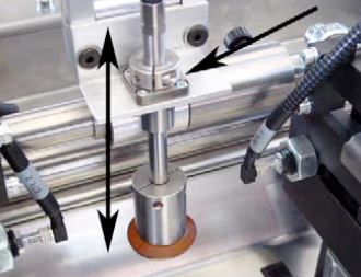
Three sensors are located on the right near the feeder drive M8.
Sensor B19 (left) controls the vacuum valve of the suction beam.


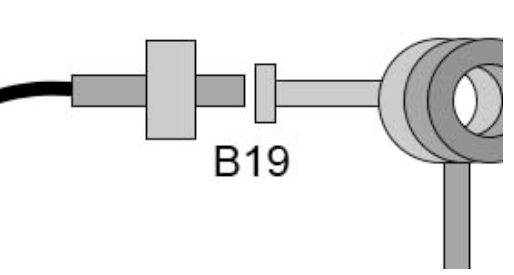
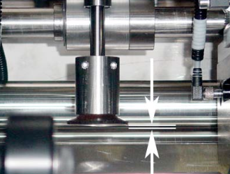
After „breaking“ the vacuum, the position of the screwhead for the sensor B19 must be active. Therefore the position should be chosen between „breaking“ the vacuum and the lowest position of the sucker unit while traveling down.
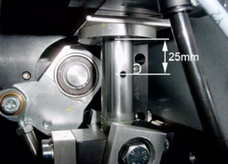


B19

The correct setting for B19 – active, should give you distance of approx. 25mm from center of the hole to the block.


B24

A hexagonal screwhead activates the sensor B24 (center), which then opens the channel flap.
NOTE:
The opening time of the channel flap, can be
extended through software (see Chapter 4.5.2. in Book 1)
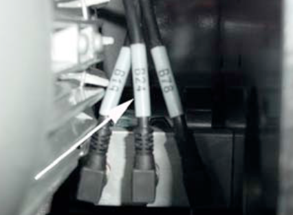
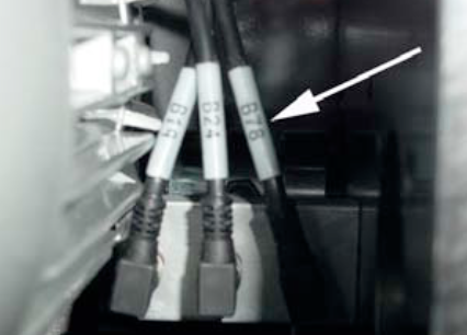
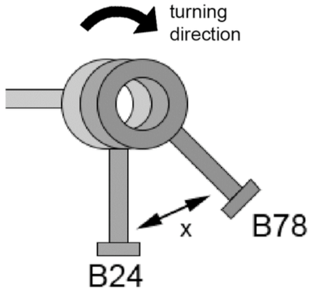
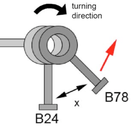


B78

A hexagonal screw activates the sensor B78 (right), which provides the timing for the feeder (synchronization)!

NOTE:
This signal comes from the PLC in the elevating platform version, so no B78 is used in such an application.


The „active“position of the screwhead for the sensor B78, can vary depending on the rollforming speed.
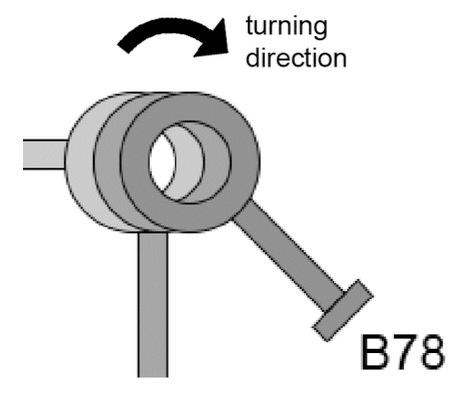


B24 B78

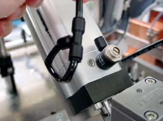
The signal of B78, always follows the signal of B24, that means that the flap must be closed (B24), before the body pusher starts (B78). The distance, resp. the angle between the two screwheads is fix (at approx. 25 – 45°).


B19 B24 B78

The correlation of the three screwheads. View from toward the electrical cabinet. This setting is based on:
Can diameter 66 – 99mm

120 cans/min

Rollformer speed of 190m/min (49.5Hz)


With a higher rollforming speed, or if the blanc feeding is too late, or you get a damaged blank beginning, you have to move both screwheads slightly clockwise.


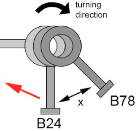
With a lower the speed of the rollformer and jams the blanks from the backtravelling body pusher, you have to move anticlockwise.


NOTE:
Make sure that the “activator” screws are tightened and locked and not touching the sensors.


NOTE:
A wrong setting of one of the sensors (B19/B24/B79) will not show a direct related error message.
An incorrect setting of B19 will cause destacking problems and the incorrect setting of B24 & B79 will cause synchronization problems.


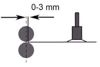
In it’s uppermost position, the sucker should lie slightly above the sheet inlet, between the first pair of rollers.


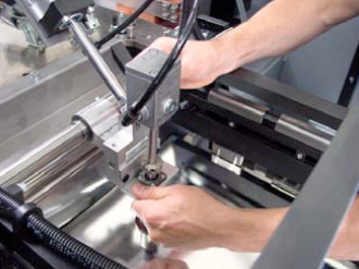
If the setting has to be changed, the screw on the setting ring will have to be loosened.


NOTE:
Further information regarding the exchange of sucker unit of the feeder can be found in Chapter 6. Changeover.


To perform a good timing, the best way is to disconnect the air hose of the cylinder and block it. In that way you can manually lift the sucker unit and find the correct timing.


If you move down the sucker unit to the blank, the vacuum will be activated. Then move up the unit together with the blank until the vacuum breaks.


The correct timing of “breaking” the vacuum is, when the blank just arrives between the roller pair.

Possible cause:

  • Wrong direction of rotation of the vacuum pump motor (only when machine has been disconnected from the power).
    • change phases
  • Clogged filter of the vacuum pump (or in the vacuum hose / tube).
    • replace it
  • Clogged bores in the sucker cups.
    • clean it
  • Worn sucker cups.
    • change sucker cups
  • Wrong vertical adjustment of the sucker bar.
    • see manual of welder (chapter 5.3) and learn how to adjust sucker bar upper position
  • Badly cutted blanks with lots of burrs.
    • grind / adjust cutters of slitter
  • Clogged vacuum valve.
    • clean it (see here) or replace valve (CM article No. 005925)
  • LED not “ON” when production “ON”.
    • refer to the electrical manual
  • Too tight adjustment of the blank magazine.
    • see manual of welder (chapter 5.3.) and learn how to set blank magazine correctly
  • Worn sucker rod or worn seals/bearing in the vacuum housing.
    • replace it

NOTE: Only applicable for the model X8-350!

All Can Man content is now also available on the Soudronic Group website.
Where do you want to continue your journey?
All Can Man content is now also available on the Soudronic Group website.
Where do you want to continue your journey?