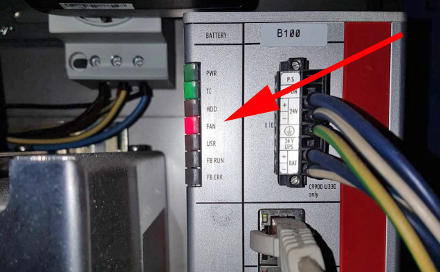
The motherboard battery is a CR2032 lithium-metal cell. It is used to supply power to the clock integrated on the motherboard. If the battery is depleted or missing, the date and time are displayed incorrectly. Recommendation for replacement interval is 5 years.
For instructions on how to replace the battery use the download link below. You will also find the correct battery type there.
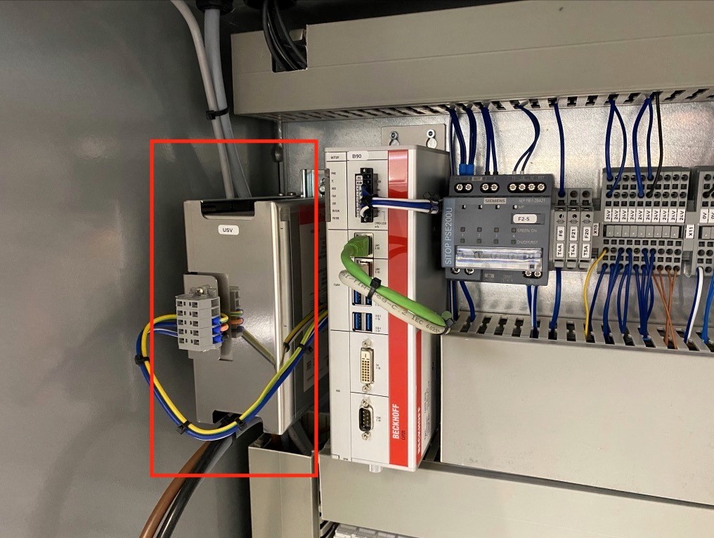
All Beckhoff control units are equipped with a UPS to ensure the proper shutdown of the control IPC. However, this only works if the battery is in perfect condition to prevent data loss and ensure the flawless operation of the control system. The battery module for the UPS must be replaced every 5 years.
To order a new battery please contact spares.canman@soudronic.com.
For instructions on how to replace the battery use the download link below. You will also find the correct order number there.
Problem:
Circuit breaker Q5 trips when the machine is switched on or during production.
Possible Causes or Resolutions:
Problem:
All drives are starting correctly, but the vacuum and welding current are not active.
Possible Causes & Resolutions:
Problem:
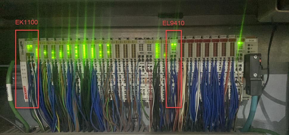
Some Beckhoff i/o terminals are not active and status LEDs are off, control does not respond to commands.
Possible Causes & Resolutions:
Problem:
After main switch off and on again, HMI piece counter values and settings are lost or old recipes are loaded.
Possible Causes & Resolutions:
Problem:
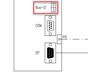
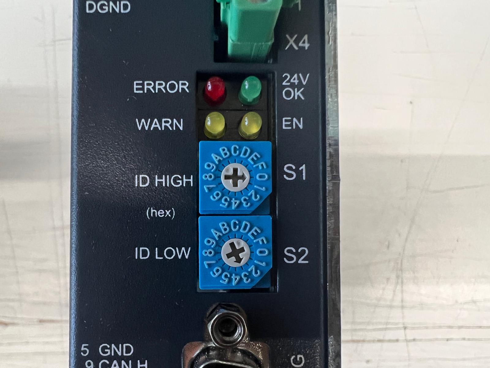
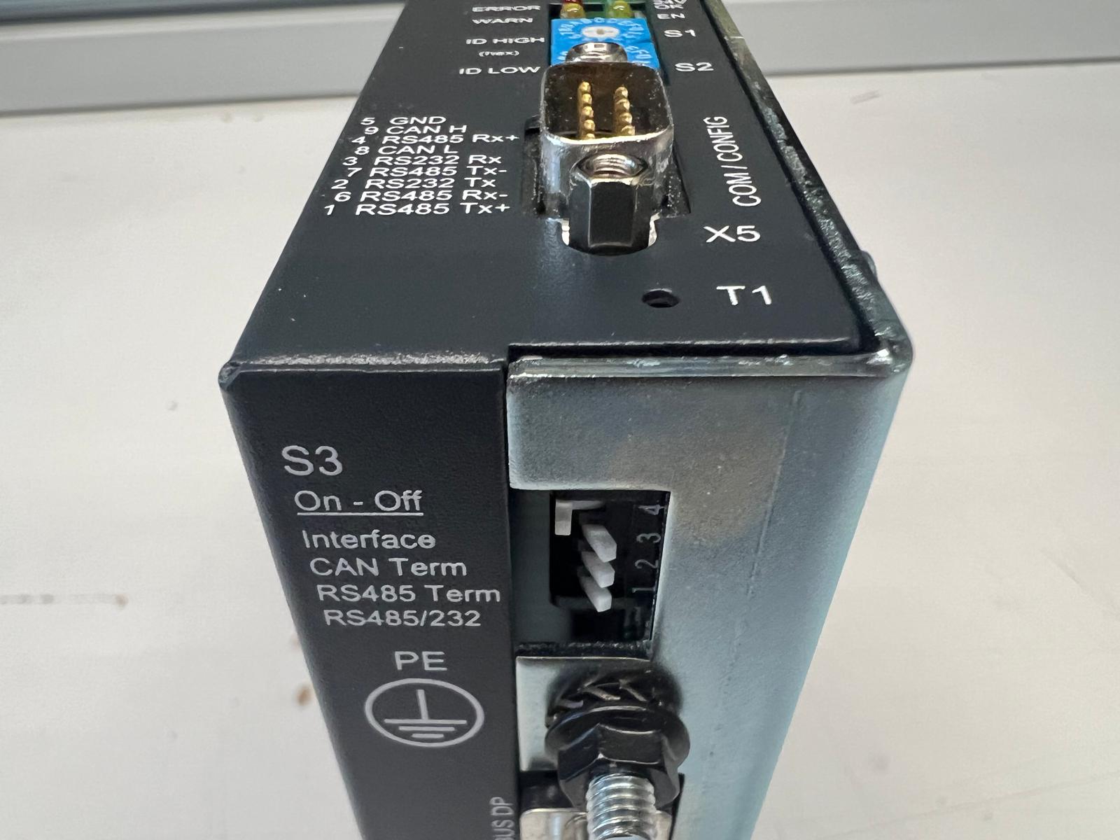
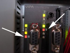
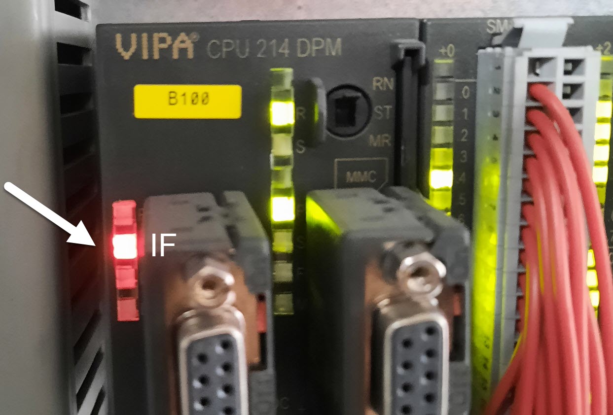
Machine stops and message „Pacemaker: Profibus communication error“ is displayed.
Possible Causes & Resolutions:
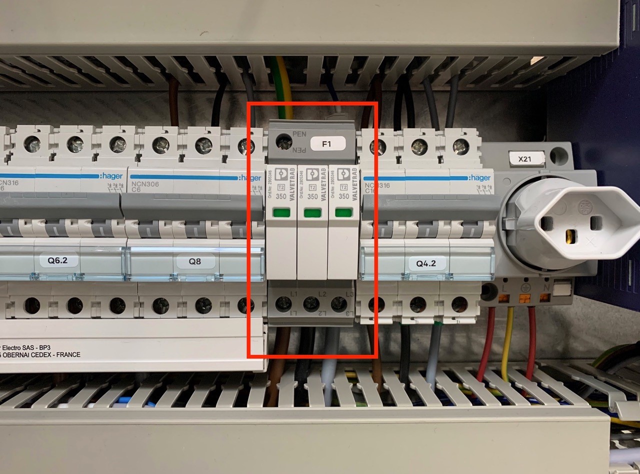
An overvoltage suppressor (or surge suppressor) is an appliance designed to protect electrical devices from voltage spikes. A surge suppressor attempts to regulate the voltage supplied to an electric device by either blocking or by shorting to ground voltages above a safe threshold.
These surge suppressors are built in to the latest Pacemaker models and machine controls (from 2009).
Check, if one or more modules of the surge suppressors are red/defect. Replace the red modules.
Attention!!!
Do not bridge the signalling contacts and run the machine with defective red modules because they no longer protect the system from voltage peaks!!!
If the modules are defective, check the main supply. Measure and check all voltages between the phases and all phases to earth before exchange the modules and restart the machine.
Possible cause:
NOTE: all timing settings are stored on the PLC and not on the memory card.
Possible Causes & Resolutions: